Resistive Location Sensing (6.9.2011) (2012)
The following experiments show the use of a simultaneously resistive and piezoresistive material (an Eeonyx Eeontex coated fabric) used to detect location of contact by measuring resistance between contact point and each of the fabric square’s four corners. I think the results look very promising, most of the inaccuracy is simply due to my poor math and programming skills. To further improve accuracy it should also be possible to use the pressure information to cancel out unwanted pressure related variations from the resistive location data. Overall i believe this solution could be much improved with some more work on the end of analyzing and mapping the sensor data. On the other hand, with this approach it would not be impossible to to gather data from multiple discrete points of contact at the same time (multi-touch). So even though this approach would immensely reduce the number of contacts needed for resolution, multi-touch seems like one of the best arguments in favor of the row/column location sensing approach – which i will try next.
First test
Based on the Knit Touchpad and an experiment using a circular piece of Velostat.
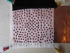
Using Eeontex RP-3-125-2B piezo/resistive fabric, which was one of the least sensitive to stretch sensing (number #8 on the stretch chart). Not being sensitive to stretch, makes it good for distance/location sensing.
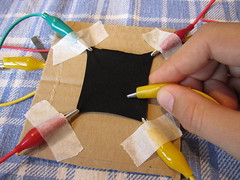
Knit Touchpad and Velostat circle:
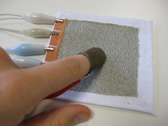
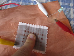
First test using Eeontex:
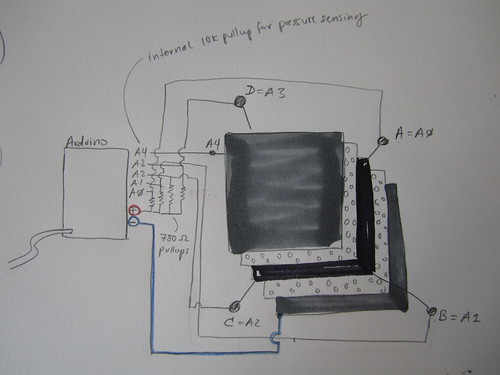
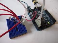
Setup using an Arduino Diecimila and external 780Ohm pullup resistors:
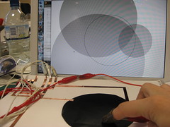
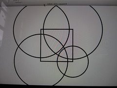
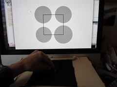
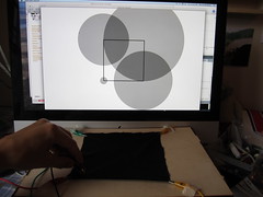
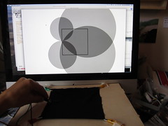
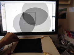
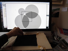
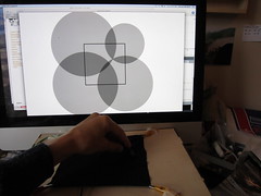
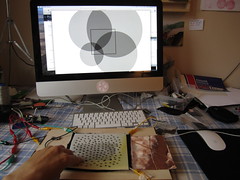
The following video shows a visualization of the resistance values measured from all four corners used to draw circles, their radius is the unfiltered sensor input, scaled to fit the square dimensions.
Linearizing sensor data
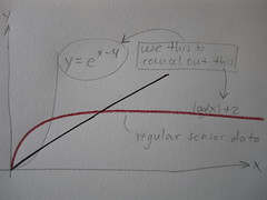
The change in resistance of the Eeontex is close to a logarithmic function, the less distance between measuring points, the more range, the further away the measuring points are the range (change in resistance) becomes less.
mappedValues[i] = map(transferValues[i], 0,1023, 0,7); // map the incoming values (0 to 1023) to a graphing range for the following calculation
linearValues[i] = exp(mappedValues[i]-4); //change from log to linear
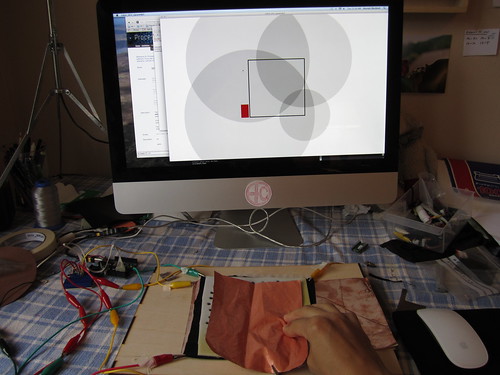
Some stills of the visualization
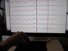
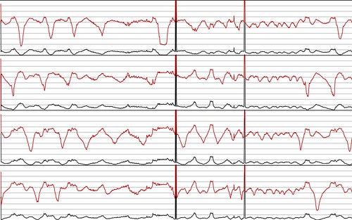
In the following video the red graph lines are the incoming sensor data and the black lines are their linearized version.
The following videos shows the same mapping as previously but this time with the linearized sensor data described above.
Eeontex fabric:
Velostat:
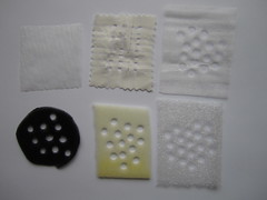
Layering and spacing
Looking for materials to build the sensor from. Soft, light and stretchy conductive fabrics from LessEMF include: silverized lycra, silverell, see-through conductive fabric, silver mesh fabric, veilshield.
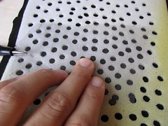
Although the best spacer material to use will best be determined by the final design of the fabric skin and how it attaches to the robot arm. How much pressure is involved in the initial fastening and what level of initial sensitivity is desired. The thicker and firmer the spacer material, the more initial pressure is needed to trigger the sensor. Spacer materials tested so far include perforated foams with different thicknesses and consistencies, loosely woven fabrics and webbing.
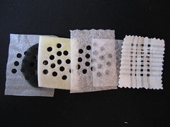
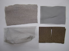
Bottom and top spacing layers in test setup
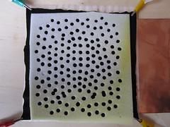
Bottom conductive layer is a sheet of copper tape, testing different conductive fabrics on top.
Adding pressure information
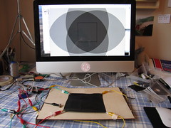
The red bar to the left of the touchpad square represents the amount of pressure applied (no matter what location). While the location sensor data has been linearized, the pressure data is not (yet).
The following video shows both location and pressure information:
Here is the schematic i used: