Programming the Arduino (2013)
If you need to edit the code on the Arduino Mini Pro microcontroller, download and install the Arduino software and drivers from here:
>> http://arduino.cc/en/Main/Software
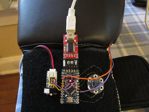
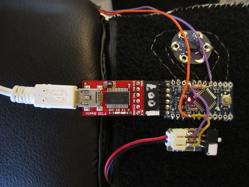
You will also need an FTDI breakout board (http://www.sparkfun.com/products/9716) and a mini USB cable to connect to the Arduino to your computer. When the Arduino is connected to the FTDI board, be sure to turn of the power switch to the LiPo battery!
Copy and paste the following code into an empty Arduino sketch and edit it as you please. From the Tools menu select the correct board (Arduino Mini Pro, 5V, ATmega328) and serial port (corresponds to your FTDI board) before pressing the upload button.
Using FTDI breakout board and mini USB cable to program Arduinos.
Arduino Code
this code is for a pair of boxing impact gloves, and is taken from tom igoe’s arduino graph code.
the code runs on an arduino mini pro, sending a series of 4 analog sensor readings (a0-a3)
out over the serial port. a sparkfun bluetooth mate silver broadcasts the serial stream to a near-by computer.
to pair the computer with the bluetooth module, enter the generic passcode “1234”.
more documentation: http://www.plusea.at/?p=2291
*/
#define numberOfSensors 4
int input [numberOfSensors];
void setup()
{
//digitalWrite(14, HIGH); // internal pull-up redsistor for analog 0 – off, because we use a 4.7K Ohm external pull-up (values from 900-300)
digitalWrite(15, HIGH); // internal pull-up resistor for analog 1 = accelerometer X (values from 230-390)
digitalWrite(16, HIGH); // internal pull-up resistor for analog 2 = accelerometer Y
digitalWrite(17, HIGH); // internal pull-up resistor for analog 3 = accelerometer Z
pinMode(11, OUTPUT); // set pin 11 as output
digitalWrite(11, HIGH); // write HIGH to pin 11 because it is connected to the + of the accelerometer
//Serial.begin(9600); // baud rate (bits per second) for USB serial
Serial.begin(115200); // baud rate (bits per second) for bluetooth
}
void loop() {
for (int count = 0; count < numberOfSensors; count++) {
int sensorReading = analogRead(count); // read each sensor
Serial.print(sensorReading, DEC); // print its value out as an ASCII numeric string
if (count < numberOfSensors -1) Serial.print(","); // if this isn't the last sensor to read then print a comma after it
}
Serial.println(); // after all the sensors have been read print a newline and carriage return
delay(10); // change the delay value (milliseconds) to control the rate of sampling
}