Working in London (2012)
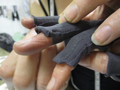
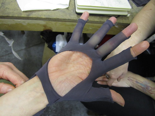
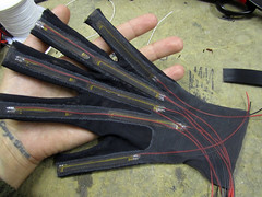
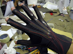
Gloves in New Fabrics


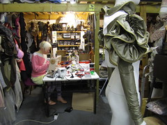
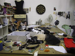
Rachel’s Studio
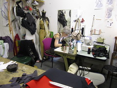
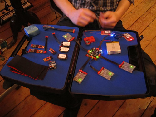
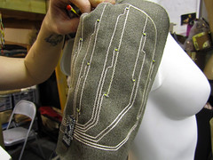
Backhub Layout


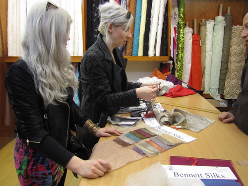
Fabric Selection

Firday Dinner


Sensor Seb’s Sensors
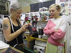
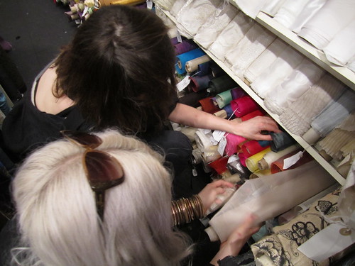
Fabric Shopping

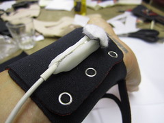
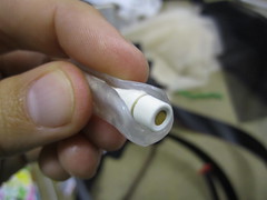
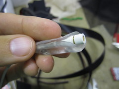
Shapelock Mic Holder


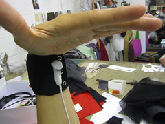
x-IMU Neoprene Tray with Powermesh Cover


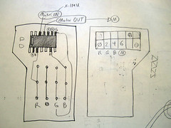
RGB LED and vibration motor driver board mod
Because of the pin-out of the SMD RGB LED we are using (MODEL NO: 5060BRG4 datasheet), i think it makes sense to choose the following AUX port connections:
Green = Aux0
Red = Aux2
Blue = Aux4
Motor = Aux6
Because of the 100mA current limit of the x-IMU:
– Light flickers when motor is on full power
– And white turns pink when motor is on full power
Photos of temporary mod to driver circuit for Wednesday deadline:
Sketches of driver circuit mod and future tapered PCB design with SMD mounted IDC connector:

Video of testing (with mistake) >> http://youtu.be/-nMOJq1F4bA
Video of it working (coming soon) >>
Internal Pull-up Resistors on x-IMU????
Plan is for Seb to figure out either:
– Use internal pullups and scrap extra circuitry
– Seb designs inline pull-up PCB with SMD mounted IDC connector
Low-profile surface-mount resistors for in-line circuit:
SMD 0805 50K Ohm resistors >> http://uk.rs-online.com/web/p/surface-mount-fixed/6620613/

In-between Finger Sensor
Modifying design to move one bend sensor from ring finger to between ring and middle finger, to measure the distance between them.
Altarnative to bend sensor: use Hall Effect Sensor for measuring distance between fingers?
DigiKey (USA) >> http://search.digikey.com/us/en/products/A1324LLHLT-T/620-1402-1-ND/2639992
RS (UK) >> http://uk.rs-online.com/web/p/hall-effect-sensor/6807116/
Datasheet >> http://www.google.com/url?sa=t&rct=j&q=&esrc=s&source=web&cd=3&ved=0CDYQFjAC&url=http%3A%2F%2Fwww.allegromicro.com%2F~%2FMedia%2FFiles%2FDatasheets%2FA1324-5-6-Datasheet.ashx&ei=sjHmTqakAs2EtgesnLzLBA&usg=AFQjCNFWwFzT6UbN3t3lr5pI_YSy7vlGyw
Magnets >> http://www.kjmagnetics.com/categories.asp

Decorative LED Circuitry
PARTS:
LED Lights:
White 1206 SMD LEDs
Digikey >> http://search.digikey.com/us/en/products/LTW-150TK/160-1737-1-ND/758709
RS >> http://uk.rs-online.com/web/p/products/7031187/

Control (microcontroller):
ATtiny85 (5 i/o pins, GBP 2.20 each)
RS >> http://uk.rs-online.com/web/p/microcontroller/6962327/
programming ATtiny with Arduino >> http://www.kobakant.at/DIY/?p=3408


Arduino Mini (20 i/o pins, GBP 13 each)
Cool components (UK) >> http://dlnmh9ip6v2uc.cloudfront.net/images/products/09218-01c_i_ma.jpg
Sparkfun (USA) >> http://www.sparkfun.com/products/9218
After Dinner Notes
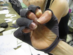
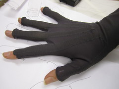
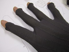
Trying on new gloves for fit
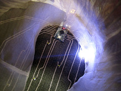
Videos of decorative lights
List of Things-to-Do
– Test decorative LED lights: embedding and control using arduino mini via x-IMU AUX port control
– Update glove wrist-band design to include x-IMU neoprene wrist tray, wired LED connections and vibration motor
– …
Saturday & Sunday
Video of gloves with differently mounted in-between finger sensors. Left hand: ring (Imogen is married to her gloves). Right hand: generic (nothing special).
Graphing in-between sensor values to compare and decide which works (and looks) best:
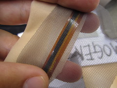
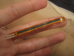
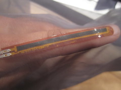
Sewing powermesh x-IMU pouch:
Thursday
Driver Board
Using Seb’s to-scale driver-board print-out we decided that we would like the board to face down/over the x-IMU. Since the board is also slightly larger (than the pull-up resistor board) this also helps eliminate strain on the connectors (board to board) from anything that might catch or push against the driver board… we remain open to suggestions.
Tweed Lights
Fixing Connections
Both the popper/snap and 14-way IDC connections are not the best… (both to be eliminated in next version).

Friday
After suit version 1 glove overhaul, all bend sensors are working beautifully: