Lightest Touch Interface (2014)
This work is a collaboration with Michael Huehmer. The aim is to build a series of sensors that react to very light touch and allow the user to have control over a very small ranges of pressure (less than 10g) exerted by the fingers. The sensor input is mapped to control the movement (up, down, left and right) and left and right button clicks of a computer mouse. The initial idea was to look at building fabric pressure sensors to achieve this goal, but we have now expanded to look at a variety of sensing techniques to capture very light touch of fingertips. We would like to thank Edupro for their interest and support in the work.
Links:
>> Photos on Flickr
>> Code on GitHub
Sensors

Test Setup
To test the sensitivities and ranges of the various sensors, an easy way to visualize analog input will be to program the Teensy to appear as a joystick when plugged in, because a joystick HID device has 6 analog inputs. A processing sketch will then graph the values of these 6 analog inputs.
>> https://www.pjrc.com/teensy/td_joystick.html
We can use the following Arduino code:
There are six functions to control the Joystick’s 6 axes. Each takes a number from 0 to 1023, where 512 is the center or resting position.
Joystick.X(value); // “value” is from 0 to 1023
Joystick.Y(value); // 512 is resting position
Joystick.Z(value);
Joystick.Zrotate(value);
Joystick.sliderLeft(value);
Joystick.sliderRight(value);
Joystick.button(num, 1); // Press button “num” (1 to 32)
Joystick.button(num, 0); // Release button “num” (1 to 32)
Download and Install Processing
>> https://processing.org/download/?processing
64 bit download link >> http://download.processing.org/processing-2.2.1-windows64.zip
32 bit download link >> http://download.processing.org/processing-2.2.1-windows32.zip
Open the example Mouse2D
Once installed, to test that processing is working, open up the “Examples” menu, and select the “Basics” –> “Input” –> “Mouse2D” sketch. Run the sketch by pressing the “play” button in the top left corner of the processing screen. A new window should open. Navigate the mouse cursor to this window. As the mouse inters the window space it will start to manipulate the squares.
Transitioning from JoyStick Test Setup to Mouse Setup
When we want to re-program the Teensy from being a Joystick, to being a computer mouse, we’ll need to update the hardware (re-plug new sensors into sockets), and the code on the Teensy.
Re-programming the Teensy
Download and Install the Teensyloader
>> https://www.pjrc.com/teensy/loader.html
windows XP download link >> https://www.pjrc.com/teensy/loader_xp.html
windows 7 and vista download link >> https://www.pjrc.com/teensy/loader_vista.html
Download and Install Arduino
>> http://arduino.cc/en/Main/Software
download link >> http://arduino.googlecode.com/files/arduino-1.0.5-r2-windows.exe
getting started (step 4, install drivers) >> http://arduino.cc/en/Guide/Windows
Download and Install Teensyduino
>> https://www.pjrc.com/teensy/td_download.html
windows installer download link >> https://www.pjrc.com/teensy/td_119/teensyduino.exe
Different Sensors to Test
Simple Fabric Pressure Sensors (eeonyx, velostat)
>> http://www.kobakant.at/DIY/?p=232
Simple Tape Pressure Sensors
>>
Capacitive Sensing
>> http://en.wikipedia.org/wiki/Capacitive_sensing
Capacitive sensing on Teensy >> https://www.pjrc.com/teensy/td_libs_CapacitiveSensor.html
Skin conductance as contact switch
>> http://en.wikipedia.org/wiki/Skin_conductance
Hall Effect Sensor and Neodymium Magnet
One idea would be to mount the magnet on the finger (possibly with nail-varnish to fingernail?) and then measure proximity between sensor and finger with nothing in between. This would also mean no force feedback to the finger to let it know how “hard” it is pressed – how close it is to the sensor.
Another idea is to mount the magnet on one side of a squishy material and the sensor on the other. Distance between magnet and sensor should be chosed to maximize range of sensor’s sensitivity, and squishy material should be chosen to be as easy as possible to “squish” and attain full range of sensor. Squishy material should also maintain it’s ability to recover, and not wear down over time.
>> http://www.digikey.com/product-detail/en/A1324LLHLT-T/620-1402-1-ND/2639992
>> https://www.sparkfun.com/products/9312
with tiny neodymium magnet >> http://www.kjmagnetics.com/proddetail.asp?prod=D11
Arduino tutorial >> http://playground.arduino.cc/Code/HallEffect
Buildr tutorial >> http://bildr.org/2011/04/various-hall-effect-sensors/
Bend Sensor as press sensor
>> http://www.flexpoint.com/companyInfo/bendSensor.htm
Bend Sensor mounted on a finger knuckle
>> http://www.flexpoint.com/companyInfo/bendSensor.htm
>> https://www.sparkfun.com/products/10264
Force Sensing Resistor (FSR)
>> https://www.sparkfun.com/products/9673
Light Barrier Sensor
a light sensor (LDR) and IR LED to create a light barrier that you can break by moving between
>> http://de.rs-online.com/web/p/products/2192533/?cm_mmc=aff-_-de-_-octopart-_-2192533
Whisker Switch
>> http://jmpswitches.com/product/whisker-switch/
Teensy Carrier Board
Circuit diagram:
Photo:
Input from Jussi
To Try:
-add at least double the capacitance of the input filter to VCC (or just put 47uF there, regardless of anything else)
-invert the voltages for the sensor (so that the signal is trying to rise from gnd when pressed)
-use internal 1.1 Vref ( check that there’s a cap and nothing else on the ref-pin ) [ analogReference(INTERNAL); ]
-just a small low-pass for the signal (e.g. 10nF, could try less than what the VREF-pin has. )
That should give a better resolution of the interesting part of signal range without changing anything too much. If the voltage goes over 1v1, and you need to determine it, just change the analogRef to something higher and measure a few more times.
Optional:
-filter the voltage to the sensor (both the sensor and the divider-resistor) with a low-pass -filter (100R + 10uF is more than enough)
-if you can do this for the AVCC, even better
-increase the size of the divider resistor from 1k, makes the conversion a bit faster, although the range might be worse. Faster conversion -> more averaging. Also, for averaging, use samples in power of 2. Math is much faster this way.
The brief peak in the voltage, when pressed and released, might be due to several things. That’s a very interesting dip. It could be that when the pad is pressed, the current draw briefly increases before the USB-cable-combination is able to provide more power. With the low-pass-filtering, the value at the analog-input pin stays stable, as it should. However, since the VCC-voltage dips, the dip goes to the AVCC and AREF respectively, causing the voltages to get a bit lower. Since those are the voltages that set the maximum analog values, if it dips, then the stable inputs will be seen as rising.
To test this: if you press the pad super-slowly, is the dip visible? If you put a smaller filter cap-does the dip become lower? If you put a big filter-cap between VCC-GND, is the dip smaller?
Also, ATtiny85 has differential ADC inputs, with a gain of x20. Unfortunately, mega328p doesn’t. You could also use t85 with adc at x20 setting. That should definitely give the resolution you need, if you use it in combination with the above. Then you could make smart “buttons” of t85, which feed the signals to the whatever arduino you want to use with the software.
Suggested Solutions:
-instrumentation amp + filter -> should get signals out of the current implementation, although I’d also add active shielding (again the electronics inside a conductive envelope, with the envelope being actively driven to a known value.)
*it already gives signals, but those are probably very faint and noisy with very light touches
-thin capacitor sandwiched inside a conductive envelope -> construct an oscillator to measure pF changes
-> very cheap, relatively stable (can be isolated), requires active pulse duration counting from arduino
-> can be very, very flat
-IF the fabric can move at least a bit, a thin magnet and a hall-effect sensor to measure the field strength, by far the easiest to interface with arduino
Questions:
-size requirements? >> see bellow
-what is the distance that the opposing sides of the touchpad can travel? (or should it remain relatively stationary? [as in <0.5mm travel])
*if it should remain stationary, then the measurement is going to be a bit more tricky, but doable
*if it can move a bit, then the distance traveled can be measured, and by proxy, the amount of force exerted on it
-is the expected signal to be linear relating to the pressure or can it be non-linear, or even non-repetitive?
*on a related note, is the expectation on a long-term continuous signal, or just short presses?
-how stable are the hands/fingers of the user in terms of hydration levels and shaking?
-how is the sensor going to be maintained? (washed, cleaned, changed to a new one? / what kinds of dirt)
Further Research on Existing Solutions
A Big Thanks to Edupro for supplying me with a free Ultra Light Switch, which activates at 10 grams.

Two other solutions by Adaptivation that take a similar approach to sensing pressure and triggering a button press are the Pal Pad and the Flexible Switch:
– Pal Pads activate at 34 grams (1.2 ounces) >> http://www.adaptivation.com/product_detail.php?ID=44
– Flexible Switch activates at less than 57 grams (two ounces) >> http://www.adaptivation.com/product_detail.php?ID=50


The Traction Pad looks like does capacitive or skin resistance sensing and activates upon touch (skin contact):
>> http://www.adaptivation.com/product_detail.php?ID=46

First Fabric Pressure Sensor Prototypes
Light Touch Pressure Sensor >> http://www.kobakant.at/DIY/?p=5210
Video
Explaining how sensors aren’t working as good ad i’d like!
Design Update
Design Sketch
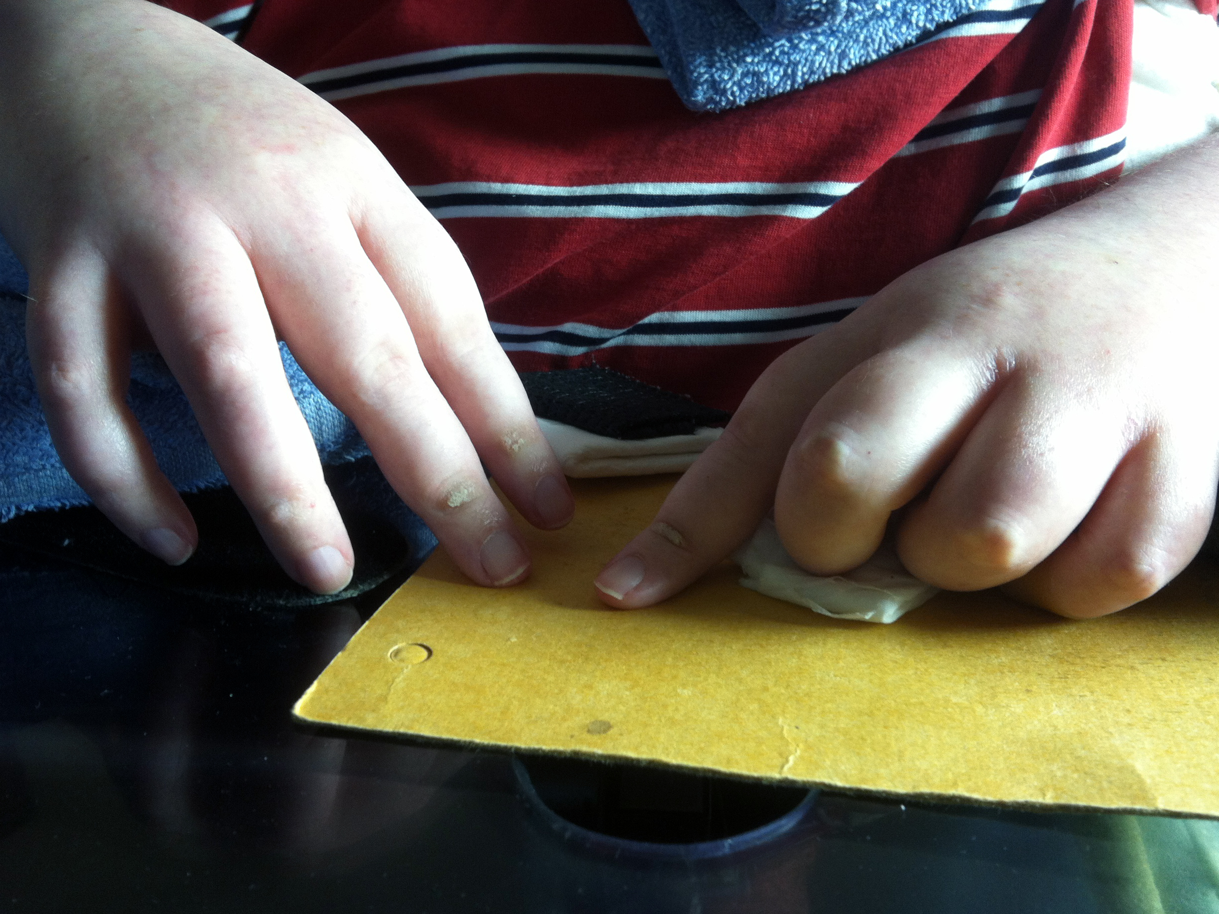
– Setup: all fingers rest on the pressure sensors at all time. Pressure sensors are triggered by pushing fingers down. Hand weight does shift a little bit
– Trigger pressure: the easiest switches to activate require 10 grams of force, so anything under 10 grams would be good
– Proposed key-combination for entering calibration mode: holding right click down, double left click and then double click UP
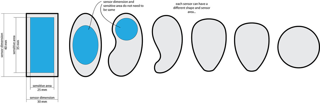
– Size and shape of pressure sensors: rectangle 2 x 3 cm (reference size is average width of finger)
– Thickness of sensors: 6-10 mm
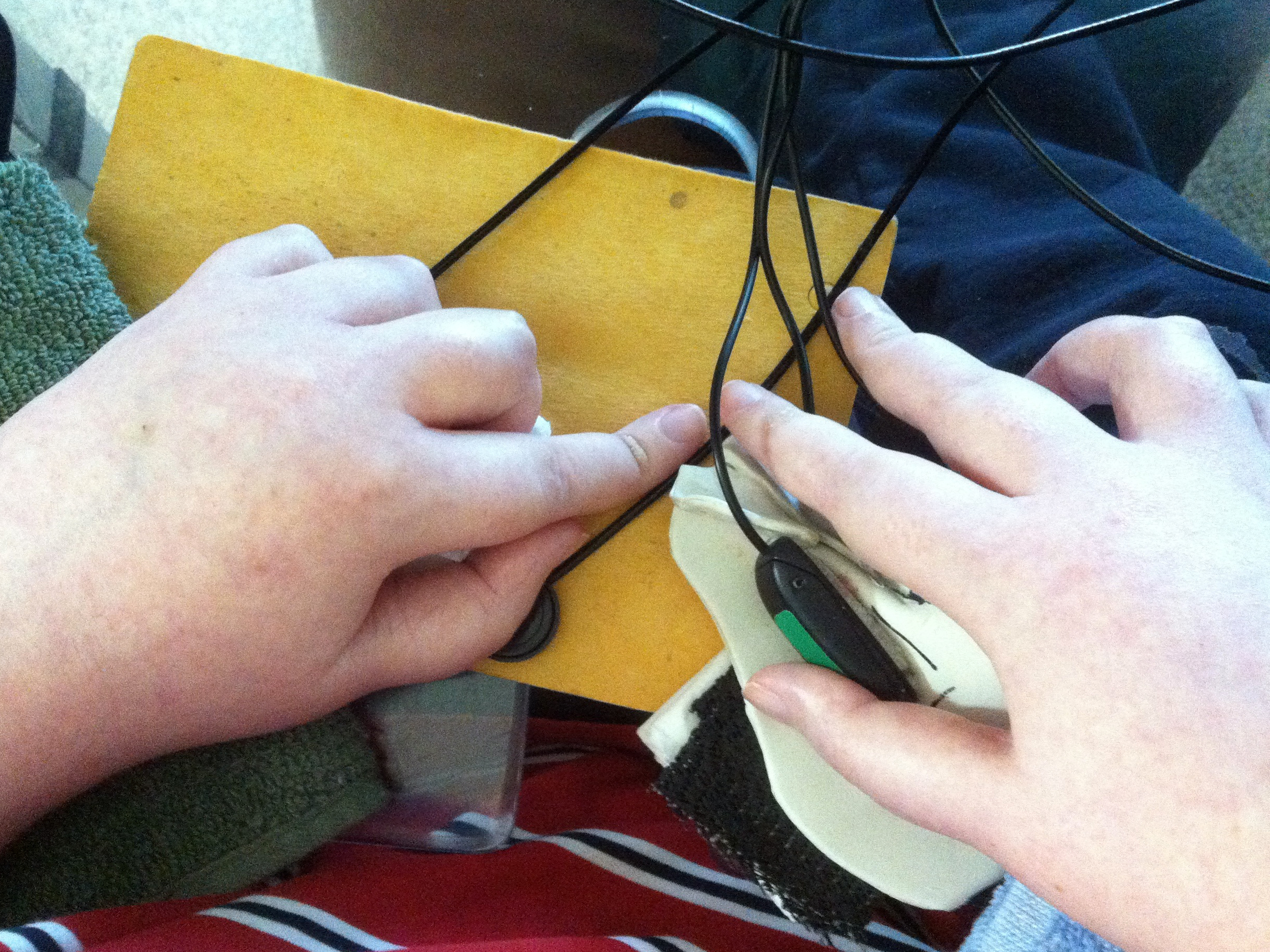
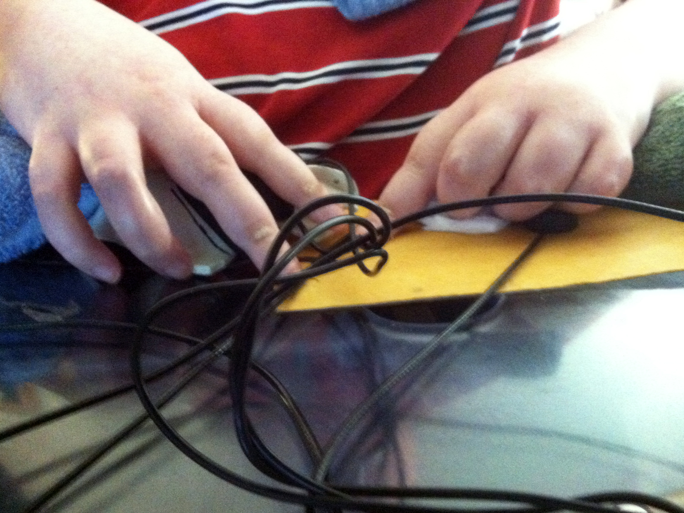
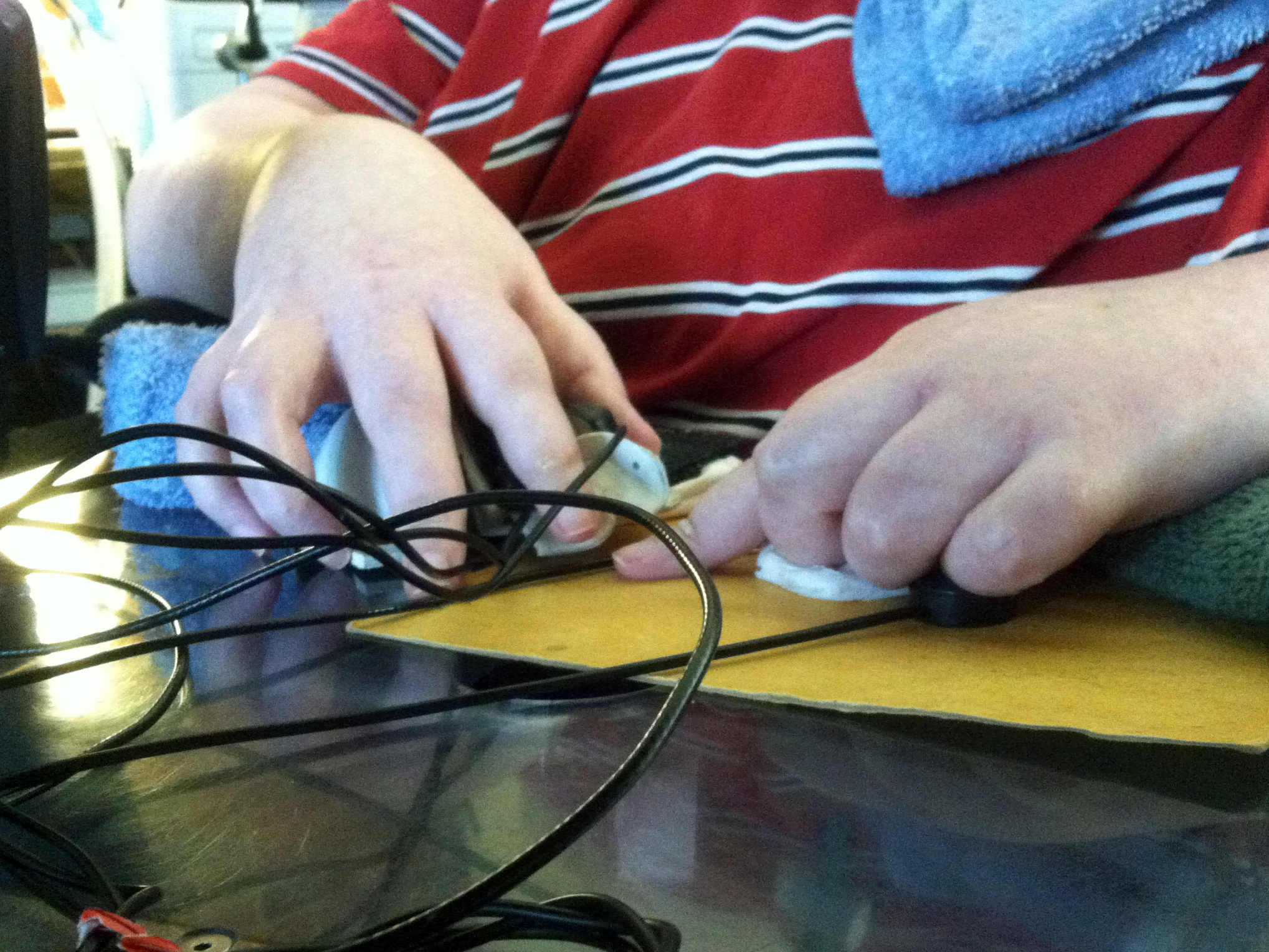
Current Interface Setup
Position of Hands
Arrangement of Buttons
– Placement of pressure sensors:
– – Three of the pressure sensors on top of the 3 existing switches for right hand
– – One pressure sensor under left thumb knuckle
– – One pressure sensor under left middle finger knuckle
– – One pressure sensor under left pinky knuckle
Overview
Current setup:
– Windows operating system
– Stealthswitch AT-10 USB Switch Interface to plug in accessible switches ($79) >> http://www.stealthswitchat.com/
– 3 Ultra Light HD Switches ($20 each) >> http://www.marblesoft.com/store/index.php?route=product/product&product_id=129
– Mousekeys feature in Windows for mousing


Problems:
– The switches are getting to hard to push
– The Stealthswitch AT can only do one key or a command like Control-V per switch and can’t do macros
To Build:
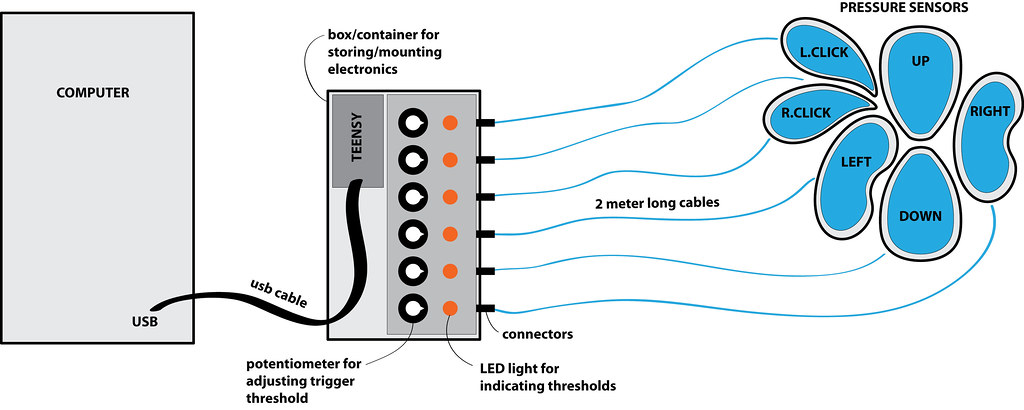
– Use Teensy 2.0 instead of Arduino for analog/digital conversion (has 12 analog pins) and HID (Human Interface Device)
– Device should be seen as a USB Mouse (HID) by any OS
– Six fabric pressure sensors (one for each mouse direction and left and right mouse buttons)
– Individual (and easily adjustable!) resting thresholds for all 6 sensors because “buttons” should not activate because of the weight of resting fingers!
– Cables from the Arduino to the sensors be approximately 1.8 meters long
– Plug connection from pressure sensor cables to Teensy
(- Bluetooth would be cool but not necessary)
To Program:
– Mouse input does not trigger until threshold is exceeded
– The mouse cursor moves faster the harder the pressure sensor is pressed
Questions:
– Size and shape of pressure sensors?
– How to set and adjust thresholds easily/conveniently?
– How to mount pressure sensors? Sticky/reusable backing? Velcro on back of buttons and velcro surface on which to arrange placement of buttons? Mounted on something solid with holes for screw mounting?
– Different colours on surface of buttons for visual differentiation? different textures for tactile differentiation?
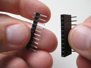
– Connections from pressure sensor cables to the Teensy? Pressure sensors should be detachable from Teensy to make replacements/fixes/changes/improvements easy. Should we go with industry standard (3.5mm mini plug and socket) or would header pin connections be okay? Other options?

Details
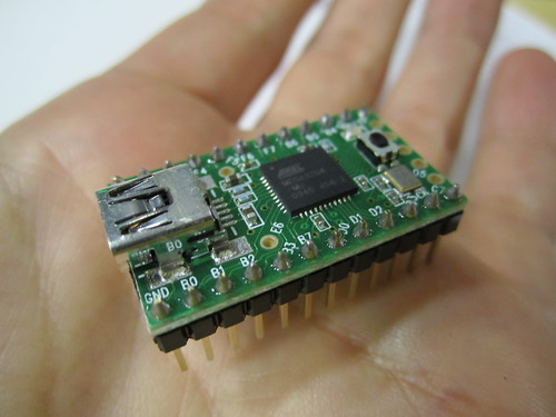
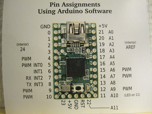
Teensy
Teensy >> https://www.pjrc.com/store/teensy.html
Handcrafting Textile Mice workshop at DIS >> http://highlowtech.org/?p=378
Pressure Sensors
Pressure Sensor Matrix >> http://www.instructables.com/id/Pressure-Sensor-Matrix/?lang=de
Video >> http://www.youtube.com/embed/3rFb-O64wL8
Thresholding

Whole System:
Materials/Costs
Electronics:
$16 Teensy
$2 long USB mini cable
Fabric materials:
neoprene
conductive thread
conductive fabric
Velostat
EeonTex
copper tape
MISC:
Wire/cables
Connectors
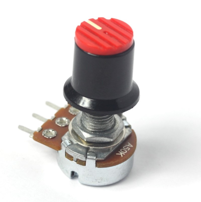
Potentiometers
LEDs for visual feedback on thresholds
Casing for Teensy (Tupperware or nice wood box)
Velcro mounting or similar