Debugging (1.11.2011) (2012)
After some trial and error experimentation, i found the major mistake in my former code for the robot skin. The bit-shifting code, that is supposed to parse the control pin combinations to read from the individual multiplexer inputs, wasn’t working at all.
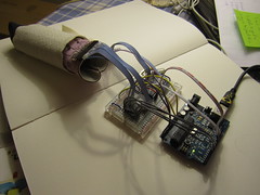
A multiplexer is a component which allows you to have more in- or outputs. It works like a gateway, and a 16-channel multiplexer has 4 control pins (ABCD) to which you send various combinations of 1 or 0 to tell it which pin (gate) to connect to.

I tried fixing my bit-shifting code, but also came across some different solutions:
Tom Igoe uses the Arduino bitRead() function >> http://www.tigoe.net/pcomp/code/arduinowiring/540
Buildr uses a two-dimensional array >> http://bildr.org/2011/02/cd74hc4067-arduino/
And others use bit-shifting code >> http://arduino.cc/en/Reference/Bitshift
I ended up implementing a two-dimensional array to store and retrieve the control pin combination values.
Here is are the code examples i used in the following video:
Arduino code >> http://web.media.mit.edu/~plusea/downloads/code/a_rSkin2Multi16.zip
Processing code >> http://web.media.mit.edu/~plusea/downloads/code/p_rSkin_11x11.zip
Video
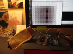
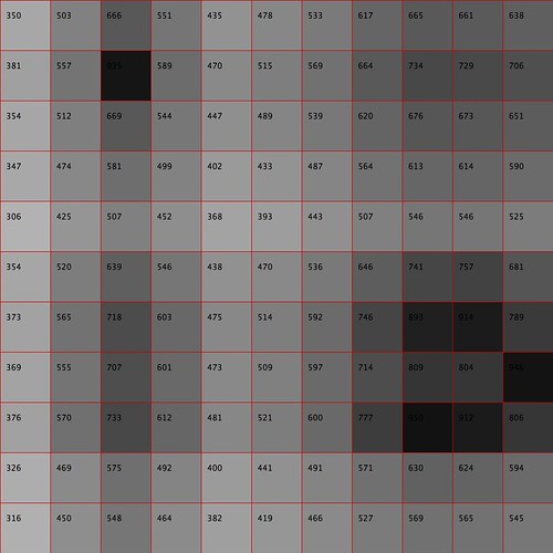
Note that the sensor data from this test setup is quite noisy and too sensitive. This is because the conductive rows and columns are made using strips of conductive fabric, rather than conductive thread as in the final prototype. The video shows: 1) Individual sensor layers disconnected for testing individual (digital) row/column connections. 2) Data stream. 3) Turning the pull-down resistor. 4) Sensor readings with Velostat in between. The Velostat seems to be providing much cleaner values that the Eeontex fabric. This will be something to look into, because in initial (flat) prototypes the piezoresistive stretch fabrics fared better.